Fuse box diagram (fuse layout), location, and assignment of fuses and relays Mitsubishi Galant (2004, 2005, 2006, 2007, 2008, 2009, 2010, 2011, 2012).

Checking and Replacing Fuses
To prevent damage to the electrical system from short-circuiting or overloading, each individual circuit is equipped with a fuse. The fuse blocks are located in the passenger compartment and in the engine compartment.
Use the fuse location diagrams and the matching tables, to check the fuse that is related to the problem. Look through the clear side of the fuse to see if the metal wire inside is separated. If it is, the fuse is blown and should be replaced. If the fuse is not blown, something else must be causing the problem. Contact an authorized Mitsubishi Motors dealer or a repair facility of your choice to have the problem checked.
There are spare fuses and a fuse puller on the cover of the instrument panel (driver's side). Always replace a blown fuse with one of the same capacity as the original.
Notice
- Before replacing a fuse, always turn off the electrical circuit concerned and place the ignition switch in the "LOCK" position.
- Do not repair fuses and never use a fuse with a capacity greater than the one listed or any substitute, such as wire, foil, etc. This would cause the circuit wiring to heat up and could cause a fire.
- If the replacement fuse blows again after a short time, have the electrical system checked by an authorized Mitsubishi Motors dealer or a repair facility of your choice to find and correct the cause.
- The fuse links will melt to prevent a fire if a large current attempts to flow through certain electrical systems. In case of a melted fuse link, see your authorized Mitsubishi Motors dealer or a repair facility of your choice for inspection and replacement.
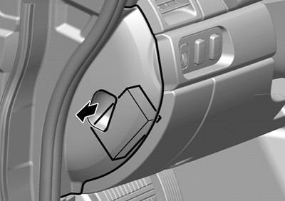
Instrument Panel Fuse Box
The fuse block in the passenger compartment is located in front of the driver's seat at the position shown in the illustration.
Fuse Box Diagram
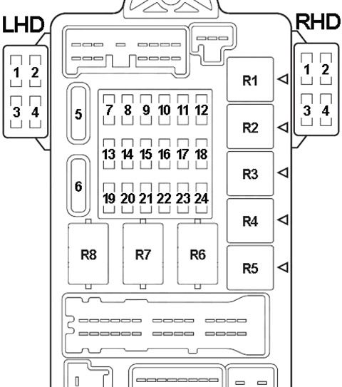
| № | A | Protected Component |
|---|---|---|
| 1 | - | - |
| 2 | - | - |
| 3 | 30 | Audio Amplifier |
| 4 | 20 | Sunroof Assembly |
| 5 | 30 | Capacitor & Rear Window Defogger |
| 6 | 30 | Blower Motor & Resistor |
| 7 | - | - |
| 8 | - | - |
| 9 | 15 | Accessory Socket |
| 10 | 15 | Data Link Connector, ETACS-ECU |
| 11 | 15 | ETACS-ECU |
| 12 | - | - |
| 13 | 7.5 | Automatic Anti-Dazzling Mirror, Radiator Sensor, Sunroof Assembly |
| 14 | 7.5 | Remote Controlled Mirror |
| 15 | - | - |
| 16 | - | - |
| 17 | 7.5 | Fuel Pump Relay, Powertrain Control Module |
| 18 | - | - |
| 19 | 7.5 | Remote Controlled Mirror (Mirror Heater) |
| 20 | 7.5 | A/C Compressor Clutch Relay, A/C-ECU, Blower Relay, Condenser Fan Motor, Fan Control Relay, Front-ECU, Heated Seat Relay, Outside/Inside Air Selection Damper Control Motor, Radiator Fan Relay, Rear Window Defogger Relay |
| 21 | - | - |
| 22 | 7.5 | A/T Control Relay, Air Bag Off Indicator Light (Passenger's Side), Input Shaft Speed Sensor, Occupant Classification-ECU, Output Shaft Speed Sensor, Powertrain Control Module, Rear Combination Light, Seat Belt Warning Light (Passenger's Side), SRS-ECU |
| 23 | 7.5 | ABS-ECU, ABS/TCL-ECU, Column Switch, Combination Meter, ETACS-ECU, Multi-Center Display Unit, SRS-ECU, TPMS Receiver |
| 24 | 10 | Ignition Сoil |
| | ||
| R1 | - | |
| R2 | Heated Seat | |
| R3 | Fuel Pump №2 | |
| R4 | Accessory Socket | |
| R5 | Fuel Pump №1 | |
| R6 | Power Window | |
| R7 | Blower | |
| R8 | Rear Window Defogger | |
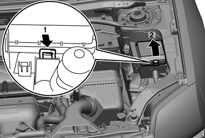
Engine Compartment Fuse Boxes
Push the lock lever, and then remove the fuse block cover.
Fuse Box Diagram
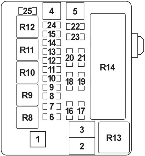
| № | A | Protected Component |
|---|---|---|
| 1 | 80 | Fuse (Passenger Compartment): "5", "6", "9", "10" |
| 2 | 30 | Radiator Fan Motor |
| 3 | 60 | ABS-ECU and ABS/TCL-ECU |
| 4 | 40 | Ignition Switch |
| 5 | 40 | Front Power Window Regulator Motor, Power Seat Assembly, Power Window Main Switch, Rear Power Window Regulator Motor, Fuse (Passenger Compartment): "4" |
| 6 | 15 | Fog Lamp and Fog Lamp Relay |
| 7 | 20 | Heated Seat Assembly, Heated Seat Switch |
| 8 | 15 | Horn (High), Horn (Low) and Horn Relay |
| 9 | 20 | Camshaft Position Sensor, Crankshaft Position Sensor, Engine Oil Control Valve, Evaporative Emission Purge Solenoid, Evaporative Emission Ventilation Solenoid, Exhaust Gas Recirculation Valve, Heated Oxygen Sensor, Injector, Mass Airflow Sensor, MFI Relay, Powertrain Control Module, Throttle Actuator Control Motor Relay, Variable Air Intake Solenoid |
| 10 | 10 | A/C Compressor Assembly, A/C-ECU |
| 11 | 15 | ABS-ECU, ABS/TCL-ECU, High-Mounted Stoplamp, Powertrain Control Module, Rear Combination Lamp |
| 12 | 10 | Rear Fog Light, Rear Fog Light Relay |
| 13 | 7.5 | Generator |
| 14 | 10 | ETACS-ECU, Hazard Lamps |
| 15 | 20 | A/T Control Solenoid Valve, Powertrain Control Module |
| 16 | 10 | Right Headlamp (High Beam) |
| 17 | 10 | Left Headlamp (High Beam) |
| 18 | 10 | Right Headlamp (Low Beam) |
| 19 | 10 | Left Headlamp (Low Beam), Headlight Leveling Switch, Headlight Leveling Unit |
| 20 | 7.5 | A/C-ECU, A/T Selector Lever Position Illumination Light, Air Bag Off Indicator Light (Passenger's Side), Combination Meter, Fog Light Switch, Front Combination Light (RH), Front Side Marker Light (RH), Glove Box Light, Hazard Warning Light Switch, Heated Seat Switch, Multi-Center Display Unit, Radio, CD Player, CD Changer, Rear Combination Light (RH), Rheostat, Seat Belt Warning Light (Passenger's Side), TCL Switch |
| 21 | 7.5 | Front Combination Light (LH), Front Side Marker Light (LH), License Plate Light, Rear Combination Light (LH) |
| 22 | 10 | A/C-ECU, Column Switch, Combination Meter, ETACS-ECU, Front-ECU, Key Reminder Switch, Multicenter Display Unit, Navigation Unit, Radio, CD Player, CD Changer, Satellite Radio Tuner, Theft-Alarm Indicator, TPMS Receiver, Universal Garage Opener, Vanity Mirror Light |
| 23 | 10 | A/C-ECU, Accessory Socket Relay, ETACS-ECU, Multi-Center Display Unit, Navigation Unit, Radio, CD Player, CD Changer |
| 24 | 15 | Fuel Pump Module |
| 25 | 30 | Front-ECU, Windshield Wiper Motor |
| 27 | 120 | On the Battery Positive Terminal: Battery, Front-ECU, Fuse (Engine Compartment Main Box) №: "1", "2", "3", "4", "5", "6", "7", "8", "9", "10", "11", "13", "14", "15", "22", "24", "26" |
| 28 | 40 | Fuse (Passenger Compartment): "3" |
| | ||
| R8 | Fog Lamp | |
| R9 | Horn | |
| R10 | - | |
| R11 | - | |
| R12 | - | |
| R13 | Fan Control | |
| R14 | Front-ECU | |
Relay Box №1
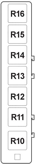
| № | Relay |
|---|---|
| R10 | - |
| R11 | - |
| R12 | Throttle Actuator Control Motor |
| R13 | - |
| R14 | A/T Control |
| R15 | MPI Control |
| R16 | A/C Compressor Clutch |
Relay Box №2
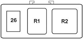
| № | A | Protected Component |
|---|---|---|
| 26 | 20 | Condenser Fan Motor |
| | ||
| R1 | Condenser Fan | |
| R2 | Rediator Fan | |
This website uses cookies to improve your experience. We'll assume you're ok with this, but you can opt-out if you wish. Cookie settingsACCEPT
Source: https://fusecheck.com/mitsubishi/mitsubishi-galant-2004-2012-fuse-diagram
Posted by: alfredoalfredoboyantone0273033.blogspot.com

Post a Comment